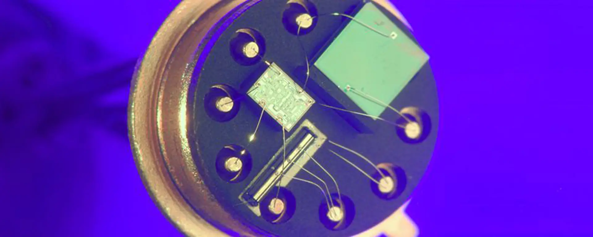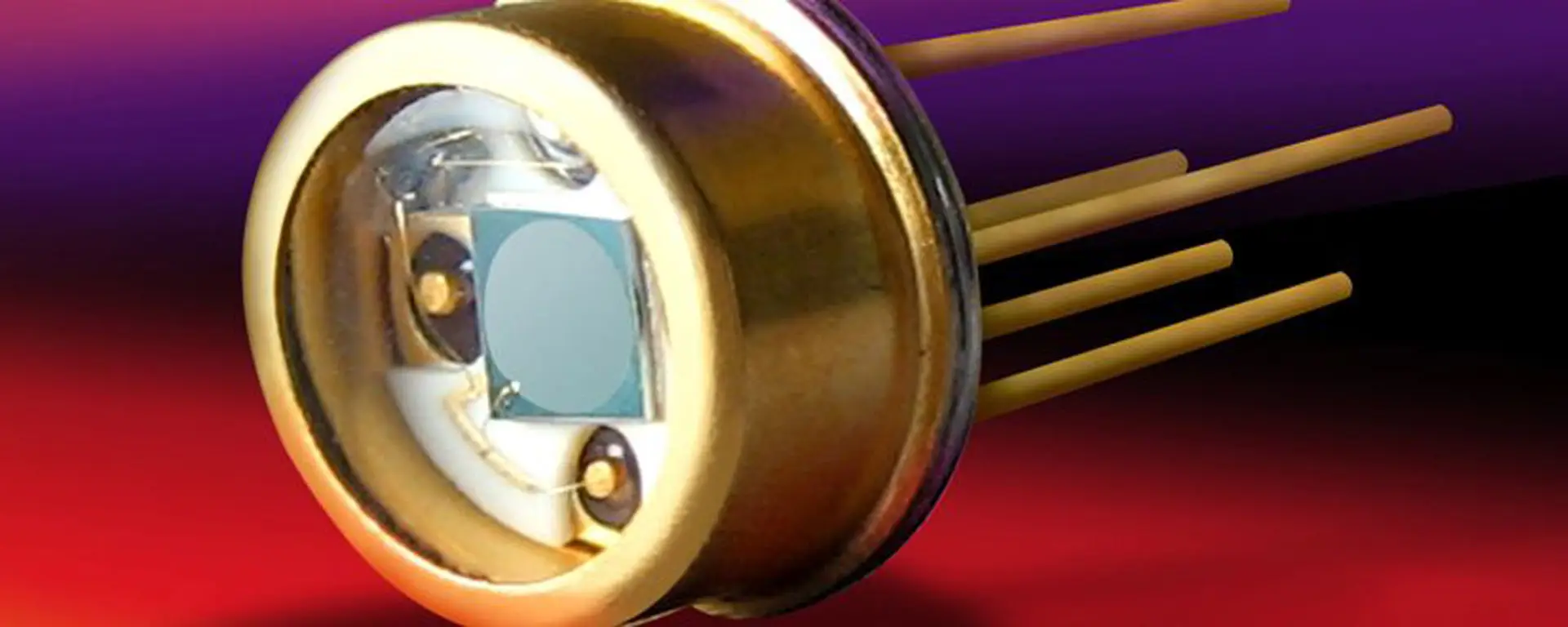
Bi-cell and quadrant silicon detectors are used for nulling, centring or measuring small positional changes in a light beam. As shown in the figure, bi-cells and quadrants are photo detectors with either two or four separate active areas, respectively.
 To understand the operation of a position sensing detector, consider the example shown, where a small, uniform, round spot of light falls on the detector. By comparing the signal received from each of the four separate quadrants, the position of the spot, relative to the centre of the device, can be determined. Specifically, x and y displacements can be approximated as shown, where A, B, C and D are the signals generated from each of the four quadrants, as shown.
 There are some constraints to be considered when using position sensors. First, the incident light spot must be smaller than the detector's total active area, but larger than the gap between individual active areas. Second, the total positional detection range is limited to the incident light spot size or the detector's active area size, whichever is smaller. Another consequence of geometry is that detection range increases with spot size, while positional resolution decreases, as shown in the figure. This is because a given movement in a small spot creates a much bigger differential signal than the same movement in a larger beam.
These rules can be summarised as follows:-
detector gap < spot size < detector size
positional range ≤ spot size or detector size
positional range α spot size
positional resolution α 1/spot size
The preceding equations for x and y displacement only hold true for beams in which a given movement of the spot always results in the same change in incident power between the quadrants, over the entire dimensions of the spot. This actually only occurs with square or rectangular spots. However, in most applications, the beam is round, which limits the linear range (position accuracy of ±5%) to the central half of the beam, as is indicated in the figure with dashed lines. These graphs still assume that the light spot is uniform. Laser beams have a Gaussian intensity profile, which further limits linear range to approximately 10% of the beam radius.
The most common use of position sensing detectors is in signal nulling to maintain constant beam alignment. In nulling the differential signal from the detector is fed back into a component which controls beam position (often a galvanometer mounted mirror), and used to restore the beam position to centre when deviations occur. Extremely precise beam alignments can be maintained using such schemes.

When performing nulling, as opposed to position measurement, it is really only necessary to compare the signal from diagonal elements on the detector. The drawing above is a block diagram for a typical such quadrant detector amplifier. For a bi-cell, a simple difference amplifier circuit may be used. If low light signals are to be detected, care should be taken when specifying first stage electronic components. In this case, the electronics noise may become greater than the signal to be detected, thus increasing the minimum detectable positional change.


