


One of the most powerful features of the PhotoniQ is in the wide variety of ways the data acquisition process can be triggered. The unit consists of an intelligent trigger module that triggers the acquisition in conventional external or internal post trigger modes. Additionally, advanced on-board digital signal processing techniques permit more sophisticated triggering modes such as input trigger and pre-trigger.
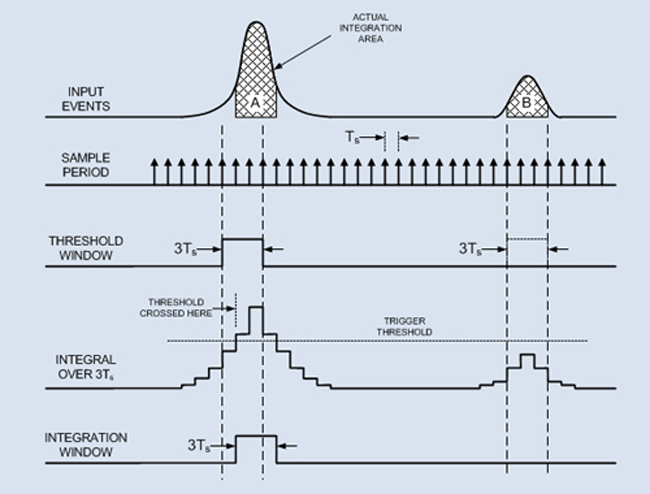 Input trigger (also referred to as event trigger) is used to trigger the acquisition process when the signal strength on a specific channel exceeds a user defined threshold. No external trigger signal is required. The integration period determines the time over which the input signal is integrated and is typically set to closely match the expected pulse width. The charge integrated during the integration time is compared to the trigger threshold level. In the example, tint equals 3Ts and event ‘A’ exceeds the threshold and event ‘B’ does not. The crossing of the threshold triggers the PhotoniQ to acquire data across all channels. To better position the integration window around the detected pulse, the actual window can be shifted by an integer number of Ts intervals (positive delay only) relative to when the threshold was crossed. This trigger mode is very useful in particle physics applications where the presence of the particle itself triggers the unit. The multiple input channels are typically configured in a spatial arrangement so that the detected signal on an individual input channel represents the energy level of a particle at a specific point in space.
 In pre-trigger mode, an external positive edge sensitive trigger signal is used to acquire event data that occurred prior to the trigger’s arrival. As shown in the figure, the programmable pre-trigger delay (tptd) is used to set the start of the programmable integration period (Tint) at a time prior to the trigger edge. The pre-trigger uncertainty time (tptu), shown as the dashed area in the figure, is equal to sampling period of the system, Ts. While the start of the integration period may be uncertain by time Ts, the actual duration of the integration period itself is quite accurate. The trigger output signal is a reference signal that can be used to setup the system. Regardless of the pre-trigger delay time, the leading edge of the trigger out always occurs between 0 and Ts from the leading edge of the trigger input signal and the period of the trigger out is precisely equal to the integration time. When the pre-trigger delay is set to one (positive) Ts, the trigger output corresponds exactly to the position of the actual integration window. For pre-trigger delay times other than zero (either positive or negative), the actual integration window is equal to the trigger output shifted by the pre-trigger delay time. Pre-triggering is sometimes used in aerosol fluorescence detection applications when delays in the user's system cause the trigger signal to lag the fluorescence event.
For a detailed discussion on PhotoniQ's powerful triggering modes, see the following application note. PhotoniQ: Triggering & Integration